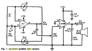
So tonight I sat down and built the thing and it didn't work at first so I did something really exciting. I entered the oscillator part of the circuit into some simulation software to see what the virtual scope thought SHOULD be going on. I wasn't able to find a 741 op amp so I went with an ideal op amp. Next I measured the resistance of both CdS photo resistors, 1st with my thumb covering the sensor and next with a desk lamp shining directly on it, fixed ~ 5cm above the surface of the CdS. This was to give me a rough range of the change in resistance. This ended up being between 2.5k and 13k. It didn't have to be exact, I just wanted to get an idea of how the relaxation oscillator was going to behave.
It turns out the original circuit didn't vary in frequency that much, no matter how much light was incident. This was due to the range of my CdS photoresistors. I took off the 'balance' potentiometer from the original Mims circuit, which nominally added 25k in series to each photo resistor and re ran the simulation. It showed a ~300Hz difference after the tweak. The cool thing about this isn't the accuracy of the numbers but the fact that I could play around with a circuit in Multisim and get an idea of what needed to be changed without having to physically build the circuit each time. This was a huge time saver.
Here is a shot of the Multisim circuit I simulated:

And here are some shots of the virtual scope output and frequency counters:

The final circuit is crude but it works! With the lights off and the use of a flash light this thing sounds pretty interesting. I recorded some audio output and ran it through some frequency analysis software which had much higher frequencies than listed in the simulation. This is due to non ideal opamp (741) and the LM386 stage, the frequency response of the output speaker (a cheap 8 ohm radio shack speaker) as well as noise from the room that was picked up from the laptop mic. Needless to say it would be nice to have an audio analyzer, a scope and while I'm at it the full version of Multisim.
Here is the finished circuit I wired up on a breadboard tonight:

Here is the original schematic:

The circuit I created omits R3, R5, C5 and C2 is 100pF.
Things to do would be add a MAX1044 charge pump so it can run off of just one 9 volt battery and of course build it into an aluminum stomp box. Also I need to take out the LM386 based audio amp stage and build something that brings it to line level output range.
No comments:
Post a Comment